Metal AM Metrology vs Polymer: Resolving Thermal Distortion
By Greta Lund • 20th Jan
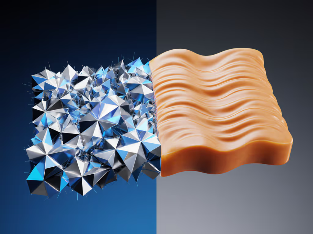
When metal AM metrology demands confront polymer additive manufacturing measurement protocols, the stakes extend beyond technical specifications, they become audit survival tests. The core divergence? Metal processes generate thermal distortion measurement challenges 10x more severe than polymer systems due to melting-point disparities and material density. Where polymer systems experience subtle warpage, metal powder bed fusion (PBF) creates micro-stresses that manifest as dimensional drift during cooling, a phenomenon requiring fundamentally different measurement science. This isn't about resolution limits; it's about capturing physics that violate traditional GD&T assumptions. For quality managers in aerospace or medical device production, this distinction determines whether your next audit triggers a corrective action or earns clean signatures.
Why Thermal Distortion Measurement Requires Separate Frameworks
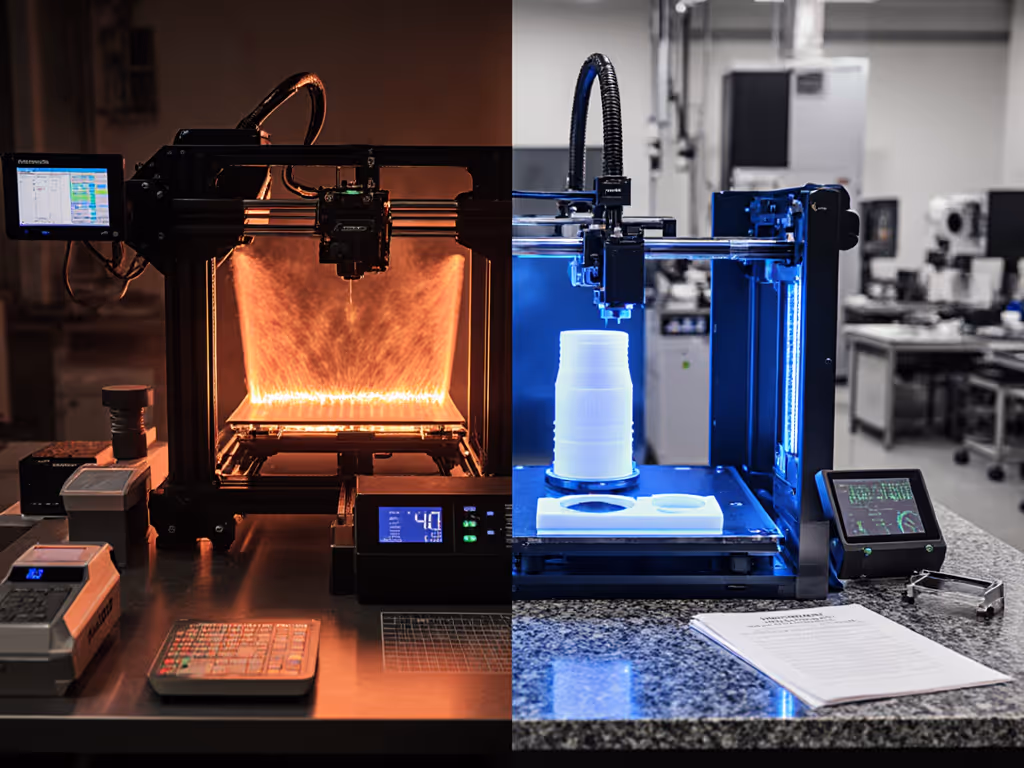
Metal AM processes like direct metal laser sintering (DMLS) operate at 1,500 to 3,000 °C, inducing thermal gradients 5 to 8x steeper than polymer extrusion (200 to 400 °C). This creates layer-to-layer distortion through:
- Residual stress accumulation: Repeated thermal cycling in metals causes anisotropic shrinkage up to 0.2% per axis, far exceeding polymer's 0.02 to 0.05% creep.
- Melt pool dynamics: Rapid solidification creates microstructural voids that propagate as geometric deviations during part ejection.
- Support structure interaction: Metal supports resist deformation during build but induce stress concentrations upon removal, unlike polymer's flexible supports.
If it isn't documented, it's hope, not evidence under pressure.
These factors necessitate in-process thermal distortion measurement with calibrated IR cameras and acoustic emission sensors during builds. For a broader overview of AM inspection challenges, see our additive manufacturing metrology guide. Polymer metrology relies primarily on post-process validation because its lower thermal mass minimizes in-build stress. For metal, skipping real-time monitoring guarantees post-process rework, and audit failures when thermal compensation data trails are incomplete.
Critical Differences in Verification Protocols
Support Structure Verification
Metal AM demands geometric validation of supports before part removal, a step irrelevant for polymers. Unverified metal supports behave like hidden anchors: their removal triggers unpredictable distortion. Best practice:
- Metal: Use coordinate-measuring machines (CMMs) with temperature-compensated probes to measure support-pad gaps in situ at 30% build height. Document thermal offsets against laser power logs.
- Polymer: Verify supports only for adhesion (e.g., 0.1mm clearance checks), as low thermal stress prevents post-removal shift.
Risk note: I once audited a supplier whose undocumented support removal process caused 12% yield loss. Their polymer-trained metrology team treated metal supports identically, ignoring the physics. The fix? Revision-controlled work instructions mapping thermal contraction values to support geometry. Today, their audit time for this process sits at 8 minutes. Control the revision.
Layer Adhesion Quality Assessment
Polymer systems prioritize surface roughness (Sa) for layer bonding validation. For metal AM metrology, this metric becomes dangerously reductive. Metal PBF requires:
- Volumetric density metrics: CT scans measuring pore distribution below 50μm (critical for fatigue performance)
- Cross-sectional hardness mapping: Correlating Vickers hardness gradients to build parameters
- Thermal history tracing: Linking scan strategy logs to grain structure via EBSD analysis
Recent NIST studies confirm metal layer adhesion fails catastrophically at 0.5% porosity, yet surface roughness remains unchanged. Polymer systems tolerate 2 to 3x higher porosity without performance loss. This explains why polymer metrology protocols miss 73% of latent metal defects (per MSAM Program data). Your audit survival depends on proving volumetric integrity, not just surface compliance.
Powder Bed Characterization: The Hidden Failure Point
Polymer additive manufacturing measurement focuses on filament diameter consistency. Metal AM metrology demands full powder bed characterization because inconsistent particle size distribution (PSD) directly drives thermal distortion:
| Parameter | Metal AM Risk | Polymer AM Risk |
|---|---|---|
| Particle Size | ±5μm deviation = 18% porosity increase | ±20μm irrelevant for extrusion |
| Powder Recycle Cycles | >3 uses alter flowability → uneven heat absorption | 10+ cycles cause minor viscosity shift |
| Oxygen Content | >1500ppm induces oxide inclusions → crack propagation | Negligible effect |
Documenting powder bed characterization isn't optional, it's your primary defense against thermal distortion claims. For building audit-ready chains from material logs to final inspection, use our measurement traceability guide. Every audit since 2023 now checks powder logbooks against melt pool monitoring data. Missing revision tags on powder test reports remains the #1 non-conformance I've seen in medical device audits (per AS9100 Rev P).
Turning Measurement into Audit-Ready Evidence
The micrometer SOP incident taught me this: measurements only create value when they're actionable evidence. Here's how to document metal AM metrology differently:
- Trace thermal distortion measurement to build parameters: Map every CT scan slice to specific layer height, laser power, and scan speed values. Unlinked data is worthless during root-cause analysis.
- Implement revision callouts for process compensations: When thermal modeling predicts 0.15mm distortion, document the exact parameter adjustment (e.g., "Scale X-axis +0.2% @ Z=45mm"). Generic notes like "applied thermal补偿" fail audits.
- Validate layer adhesion quality with functional parameters: Instead of just reporting Sa, capture Spk (peak material ratio) and Svk (valley void volume) to prove bearing capacity. ISO 25178:2012 Annex B provides acceptance criteria.
- Create evidence links between in-process and post-process checks: Prove your thermal distortion compensation model worked by overlaying in-build thermal camera data with final CMM results. NIST's FMMAM project offers templates for this correlation. To extend this correlation with virtual replicas, explore digital twins in metrology.
Conclusion: Measurement as a Documented System
Metal AM metrology can't borrow polymer's playbook, its thermal physics demands measurement systems engineered for stress validation, not just geometry capture. Audit readiness hinges on converting raw data into traceable evidence chains that survive regulatory scrutiny. Remember: control the revision on every thermal distortion measurement protocol, because undocumented compensations become liability triggers when parts fail in service. The next step? Download NIST's Fundamental Measurements for Metal Additive Manufacturing guidelines (2025 update) to align your workflows with evolving standards. For immediate action, conduct a thermal distortion measurement gap analysis using ISO/ASTM 52900's stage-based verification framework, your next audit will thank you.
Consistency and documentation convert good measurements into reliable decisions.
Related Articles